
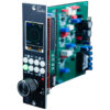
JCF Audio TE2 24-Bit 192kHz Analog to Digital Converter
$5,270.00
The JCF Audio TE2 is a High-Resolution 2 channel Analog to Digital converter with a choice of input paths in the venerable 500 format.
In stock
Description
JCF Audio TE2 24-Bit 192kHz Analog to Digital Converter
The JCF Audio TE2 is a High-Resolution 2 channel Analog to Digital converter with a choice of input paths in the venerable 500 format.
The TE2 is a High-Resolution 2 channel Analog to Digital converter for the 500 series format that draws on some of the history of the Latte and some of the history of the AD8.
The unit is a two-slot device and transmits the industry standard AES/EBU protocol through both 500 series outputs or as a dual-wire set at the behest of ajumper setting. The TE2 can derive its sync source from an internal reference at the 3 common multiples of both families of speeds, an AES/EBU input source on the Pin 6 buss, an external AES/EBU signal entering through the rear, USB software control, or optionally an incoming a word clock source. The left-hand side of the unit’s AES/EBU output becomes an input in when directed to receive sync from the rear jack. “R” denoting “Rear”, not “Right”. A simple XLR adapter can be used to do this in the case of XLR connections. Patchbays need none.
PEP processing is standard on the TE2 and can be applied to the conversion result or not. Input data from a pin 6 AES/EBU stream, the external AES/EBU input stream, or the USB return data can be processed in “D/D PEP” mode.
The analog inputs on the TE2 are available in two different forms. Differential (with an operational amplifier of choice) OR both a fully floating transformer input in addition to the differential input. In the “both” model the input style is chosen with jumpers. Both input styles provide isolation and good commonmode rejection figures essential for studio environments. When using the transformer coupled input configuration with the TE2 polarity should not be inverted with unbalanced sources by feeding pin 3. A small amount of high frequency loss will occur. There are a number of digital input options that are available to get data into PEP for loop processing that are covered in the data graph further into the manual.
Front Panel Controls
Level – These level adjustments at the top of both sides of the unit control the sensitivity of the A/D input in 1dB steps. Accompanying these controls are two vernier trimmers accessible through holes in the front panel. The trimmers provide approximately 1dB of adjustment in each direction to center the scale. The 6 step scale covers a sensible range of calibration levels for both transformer and differential input styles. Calibration level details are listed in the Specifications section.
Clock– The lower right hand switch selects the clock source of the unit. The selections are the 6 standard pro audio speeds with an internal time-base, clock derived from a bi-phase input on 500 series pin 6, clock derived from a bi-phase input through the left hand side output, clock as prescribed from the driver of the USB connection, or Word Clock/Off (with optional card). If the Word input card is not installed the unit will either output AES with all zeroes for data at 44.1kHz or halt operation completely depending on the setting of J1. It’s important to note that this control sets the clock for the TE2 only. It has no bearing on data flow or where it is routed internally. All external sync modes are set-and-forget which means there are no physical adjustments to make when changing speeds.
Data – The lower left hand switch selects the operable data mode for the unit. “A/D” selects for the ADC conversion result passed directly to the available digital output streams. “A/D PEP” selects for the ADC conversion result passed to PEP and then passed to the available digital output streams. “D/D PEP” selects for a digital input stream to be passed to PEP and then back out to at least one digital output as available under the current mode. The data flow graph section details this.
Clip Indicators – This indicates that the ADC conversion block has been overmodulated. Per channel indication with a sensible reset time. Important to note that an over on either channel will restart the reset time for both channels.
Frequency Indication LEDs – These indicate what speed the unit is operating at whether selected from internal time references or external.
SE – This Sync Error LED indicates that the sync source selected is invalid and data from the unit is not to be used.
Word Clock Input – This BNC jack (if present) accepts a standard TTL level word clock input. The input is 75 ohm terminated and differential with a high impedance common reference. The input signal is reasonably well-conditioned and doesn’t really have a preference of shape or duty cycle. A hole plug is present if the Word Clock module is not installed.
Features
- Low group delay without PEP engaged
- Highly configurable clocking
- Sleek Dual 500 slot design
- Two different input styles
- ~7W consumption
- PEP processing standard
To learn more about JCF Audio ,Click Here
Additional information
| Brand | JCF Audio |
|---|---|
| Condition | New |
Technical Specifications:
- D/A Calibration Range:
- MIN:
- - Level fully counterclockwise
- +22dBu = 0dBFS | +4dBu = -18dBFS
- MAX:
- - Level fully clockwise
- +17dBu = 0dBFS | +4dBu = -13dBFS
- Emphasis is not used in the TE2
- Power Consumption: < 07 Watts
- Input Impedance:
- Differential amp input path: 40k(CM)
- Transformer input path: ~2k7
- Frequency Response (relative to 0 @ 1k):
- 48kHz : 20Hz -0.1dB | 20kHz -0.1dB
- 96kHz: 20Hz -0.1dB | 20kHz -0.1dB | 30kHz -0.2dB | 40kHz -1.5dB
- 192kHz : 20Hz -0.1dB | 20kHz -0.1dB | 50kHz -0.2dB | 70kHz -2.2dB
- Shipping weight: 4 lbs. 11"X 11"X 6"